Jan 1:
The project that will never get done. Due to my new intense dislike for vmware on osx,(probably as a result of vmware letting go of the whole team a while back) I’ve switched to docker. It took about a week of my spare time to get things more or less the way I want them.
The Dockerfile I ended up with is: (ymmv):
FROM wolfeidau/esp8266-dev:1.4.0

RUN apt-get update && apt-get install -y \
 zlib1g-dev \
 default-jdk \
 curl

# add all the SDK stuff to the PATH
 ENV PATH=$PATH:/opt/Espressif/crosstool-NG/builds/xtensa-lx106-elf/bin

# this needs the trailing slash
 ENV XTENSA_TOOLS_ROOT=/opt/Espressif/crosstool-NG/builds/xtensa-lx106-elf/bin/
 ENV SDK_BASE=/opt/Espressif/esp_iot_sdk_v1.4.0

# Path which contains your esp8266 project source code
 WORKDIR /Volumes/MacHD/Users/chuck/Organized-Projects/CarGauge/Build/esp-gauges

# pass -v /Users:/Users to ensure your shared folder is available within
# the container for builds.
 VOLUME /Users
 VOLUME /Volumes/MacHD/Users

RUN echo "root:Docker!" | chpasswd

USER ubuntu
I’m also using obdsim on mac using the obdgpslogger-0.16.tar.gz version (in the Tarball section) from this link.
You need to navigate to the downloaded folder and then run the commands:
mkdir build
cd build
cmake .. (I installed this with brew, which needed the newest xcode)
make
make install # optional
This whole digression is very reminiscent of yak shaving
Oct 31:
More minor progress. Communication is better, but slow. Gauge PIDs are selectable through the U/I. Now to just pretty up the displays a bit.
Oct 6:
Now with case… I spent a couple of nights CNCing, and now have a case, 1/8″ acrylic in front and a spacer for the boards to fit into and a back, that has some pocket cuts for some of the larger parts, the LDO, usb mini jack esp8266, and a slot for serial port access, in case I really mess up an pooch the OTA capability. Back to writing S/W I guess. Oct 4:
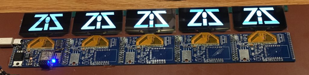
It’s getting there. I’ve got five displays daisy chained now; selectable with the demultiplexer. Just tonight I’ve folded the displays over to the back of the board and held them down with 3M VHB double stick tape. For development, I’m talking to obdsim on a linux vm to write the software. So far, software-wise, I can initialize the controller, and query the OBD for the available PIDs. I got a little bored of the SW and want to start building a case for the displays now. Since the wifi OTA updates work great I’m confident that having the displays “case-ified” won’t be a problem at this stage of the game.
Sept 6:
As you can see (way) below I’ve added the ELM 327 dongle to setup the and hooked up the UART through the mini USB connector. After booting the module, connecting to the AP and telnetting in :
mac-mini:~ chuck$ telnet 192.168.4.1 23
Trying 192.168.4.1...
Connected to 192.168.4.1.
Escape character is '^]'.
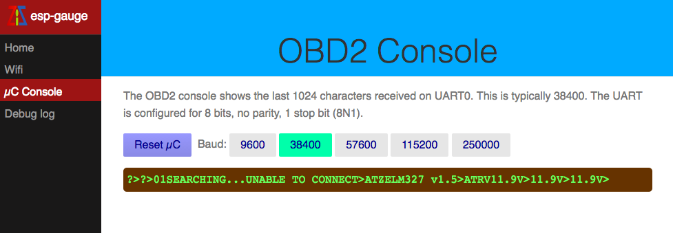
And setting the baud rate on the web page: I’m talking to the dongle:
>01
SEARCHING... UNABLE TO CONNECT
>ATZ
ELM327 v1.5
>atrv
11.9
Here is the web page log, along with the baud-rate selection buttons:
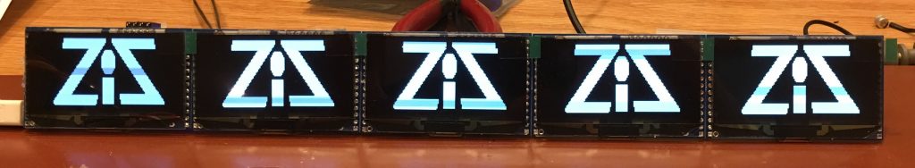
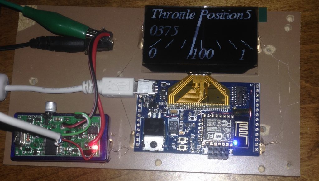
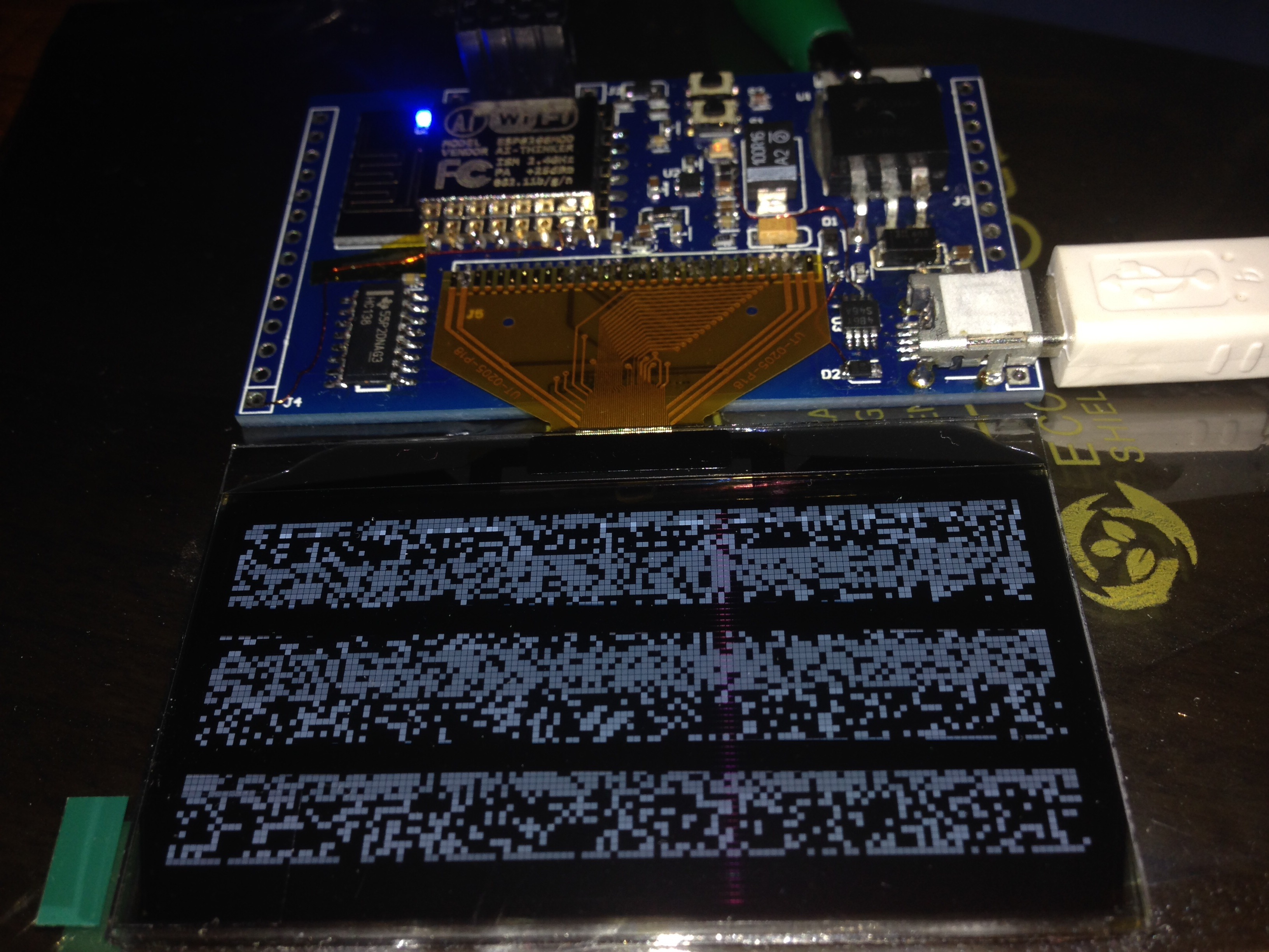
Here is the current hardware setup. It is a little more stable now that it is glued down!
Sept 5:
I’ve done a bit more investigating on the power up problems. So purely empirically, when the display is running, if I cut and reconnect power before the 13V supply charge pump cap drops below about 12V, the display works. Failing that I need to wait about 90 seconds before applying power (when the voltage at the cap is at about 6V). What is weird is that if I short the cap to discharge the 13V supply it still does not come up, so it seems that the display is rather particular about how it is powered on.
This could easily still be a software problem. More digging is required! There are power up timing constraints in the data sheet which I am completely ignoring:
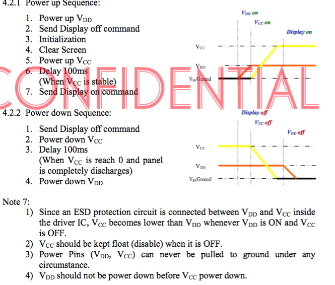
Oh well.
Another Update Sept 4:
The board is getting really messy now. I reworked the board to use the hardware SPI chip select, instead of bit banging. This required using an inverting input on the HC138 (decoder/mux). After a bit of software rework, voilà, we’ve got an image. So it occurs to me that the reason the software CS probably didn’t was that the signal was inverted going through the mux. Oh Well. I’m not out of the woods yet however, since there is a power up sequencing issue that I need to solve. The upshot is that I need to leave the display unplugged a couple of minutes before the display boots correctly. More to come. Long weekends rock!
Update Sep 4
I soldered on the OLED display. It’s alive. Sort of. So I think electrically it is probably ok, I suspect the chip selects, or startup timing. Baby steps.
Update Sep 3
Work is slowly progressing on board bring up. So far there have been two errors in the board design.
- The boost converter to make the 13V for the oled cannot have 10v on the logic portion of the chip. This bit was reworked.
- mosi and miso were swapped on the esp8266-12E module schematic part in protel, whoops.
Work is progressing on the software as well, the mux is now in a state where it should work for selecting the onboard display. Next steps are to solder on the OLED when I’m feeling brave.
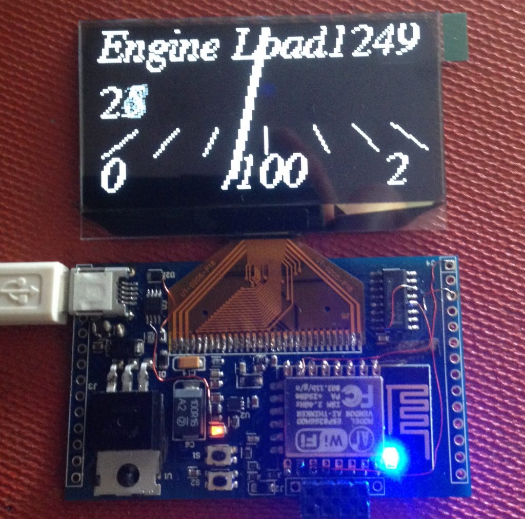
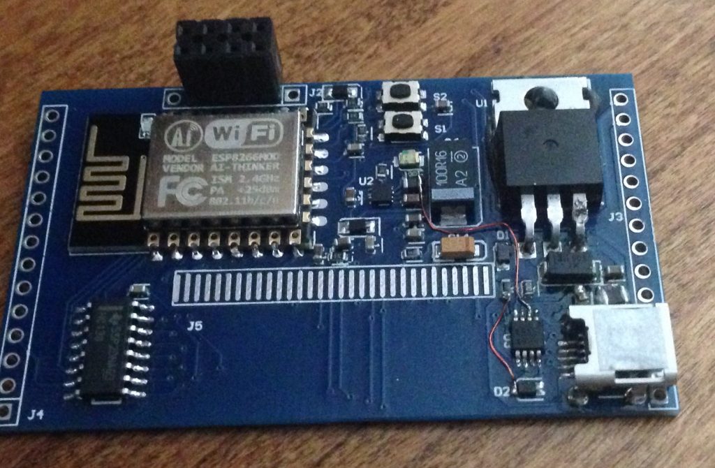
Here is the current state of the board:
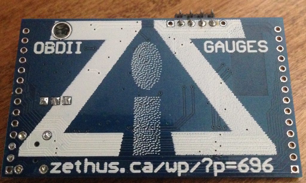
 This page is reserved as doc for the car gauges in case anyone comes here based on the
silk screen doc from dirtypcb. This will be fleshed out as work progresses.
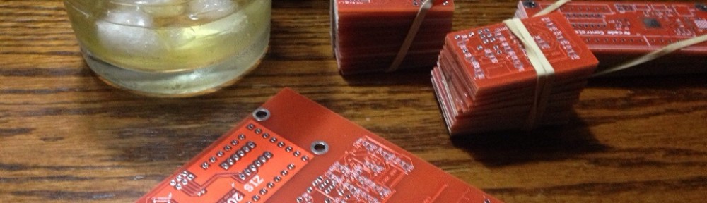
Boards are off to fab soon, here is the teaser gerber: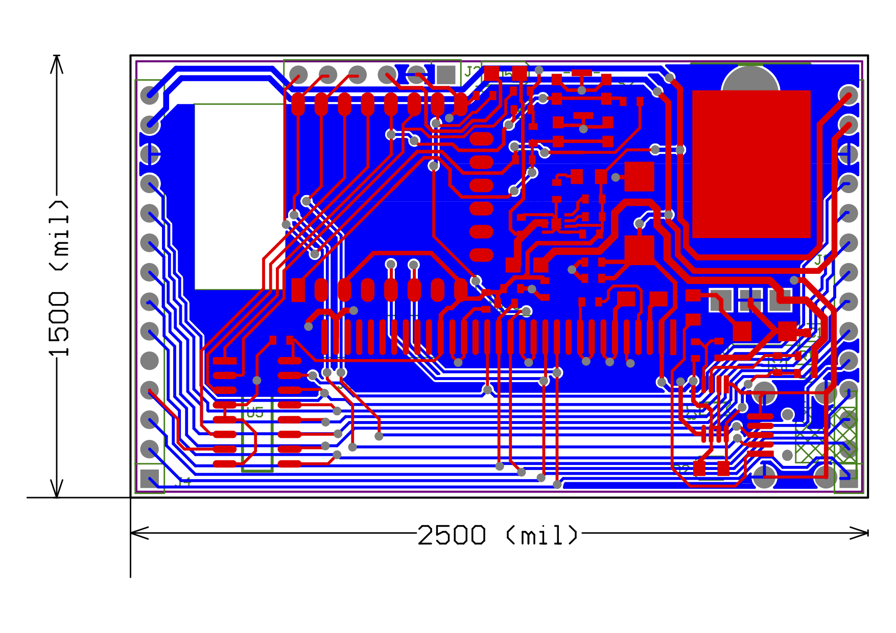
The basic premise is that a cheap OBD II dongle will interface with these boards to display data on an OLED display. The display boards are designed to be daisy chained together so that up to 5 (five) boards can be controlled with one ESP-8266.