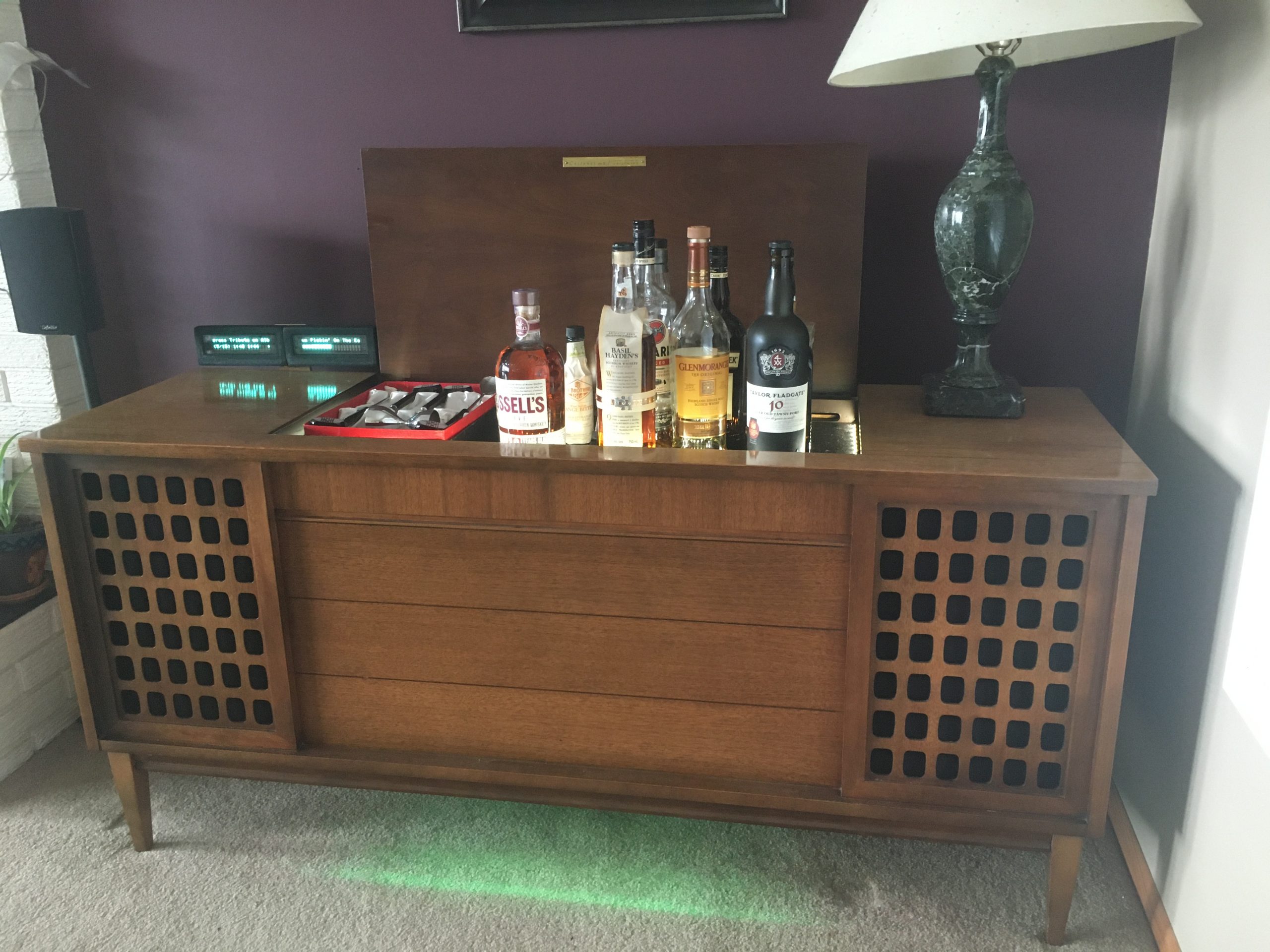
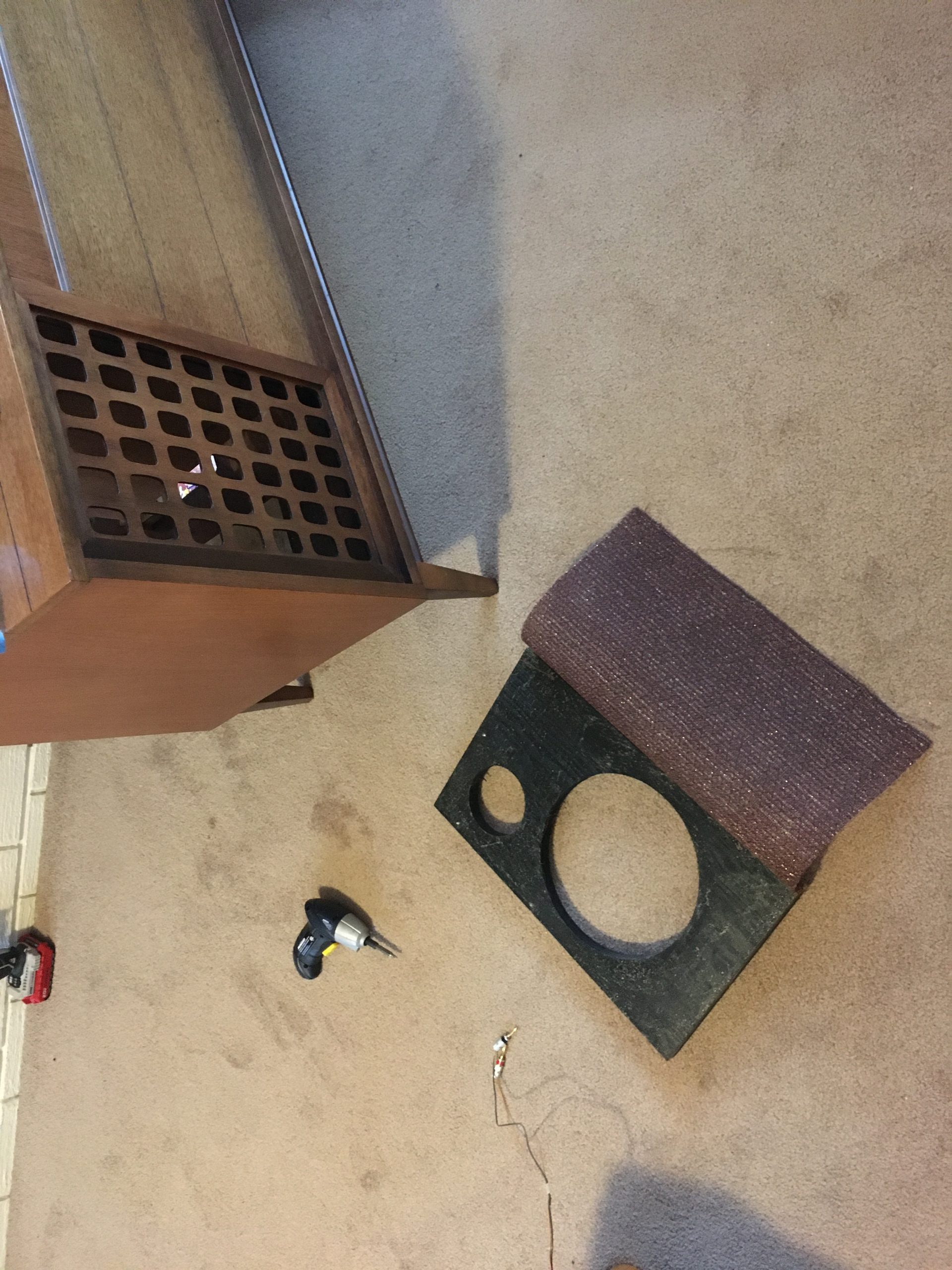
For this installment I’ve turned my mom’s old console stereo into a liquor cabinet. I’m sure she would not have approved and she passed before I could show her the result. The old console stereo was comprised of a tube receiver, and turntable. It was built in the late ’50s. The sound was not spectacular, but not bad either. I’d replaced the woofers in this unit about 20 years ago, and they have not disintegrated yet. The dust caps fell off, but the foam surrounds are still solid.
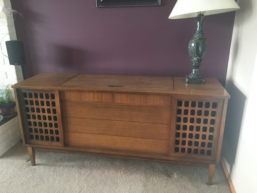
unassuming “stereo” cabinet 
open liquor cabinet

For this build, I wanted an funky cabinet that would look original but actually be useful with something newer than 50 year old technology. The features include:
- Linear actuator to control opening cabinet
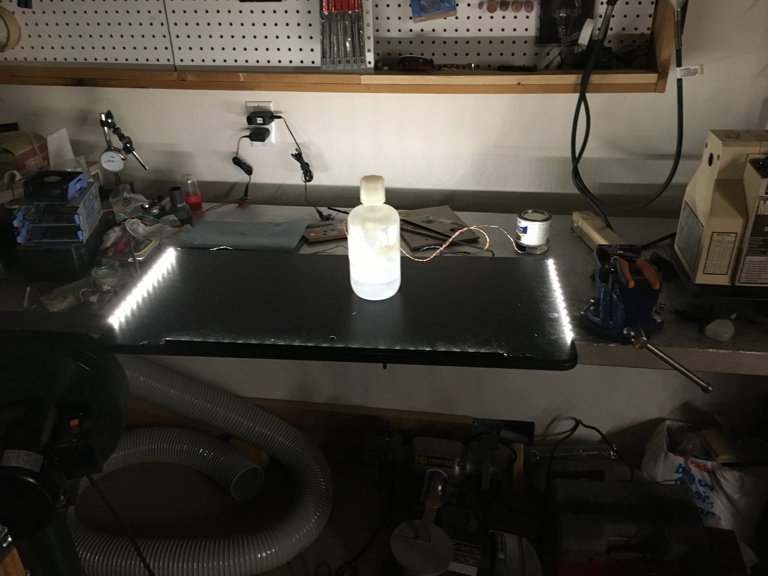
- Interior lighting for bottles
- Logitech Media Server based synchronized multi-room audio system
- Vacuum fluorescent display (VFD) for music information.
- VFD on a linear actuator so it “hides” when music is not playing
- RGB VU meters as “ground effects” in the cabinet.
- Capacitive controls for raising and lowering booze
- Web page for lighting and cabinet control, as well as music playback
This first part of the build was demolition:
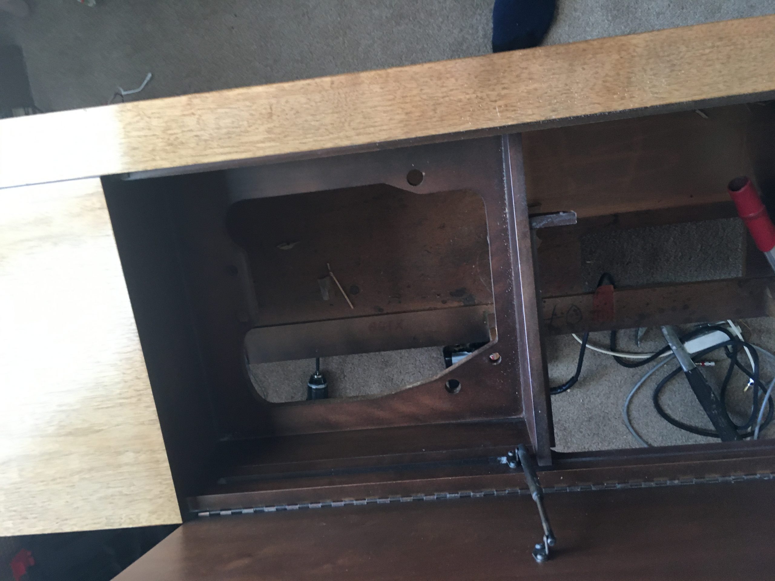
Beginning of teardown 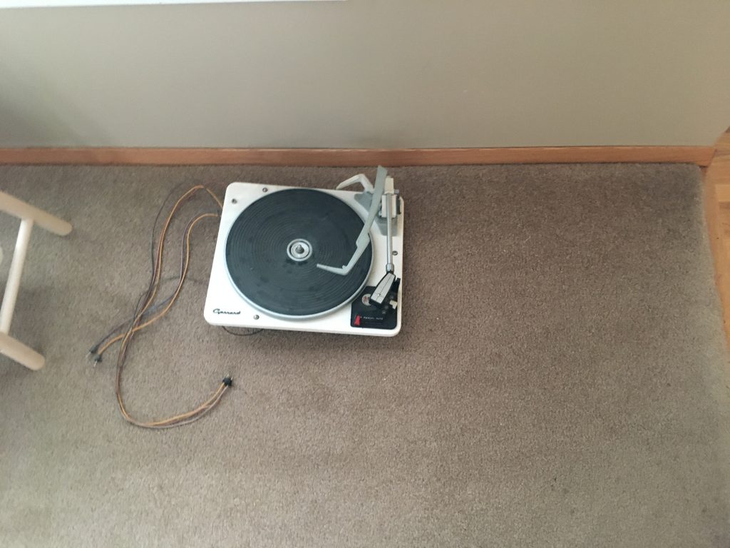
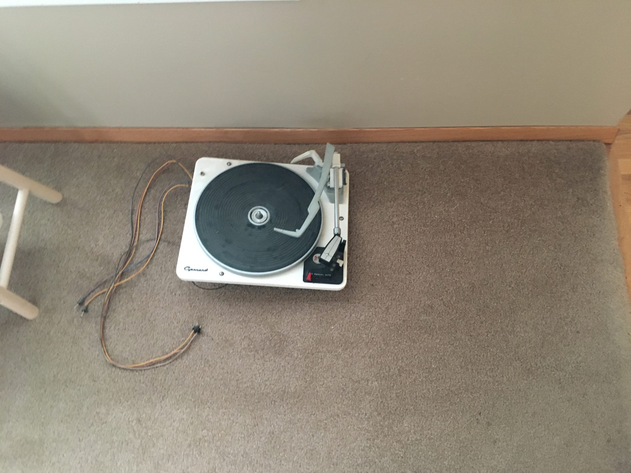
Old Turntable
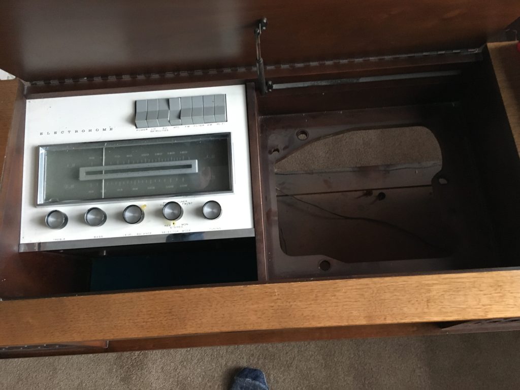
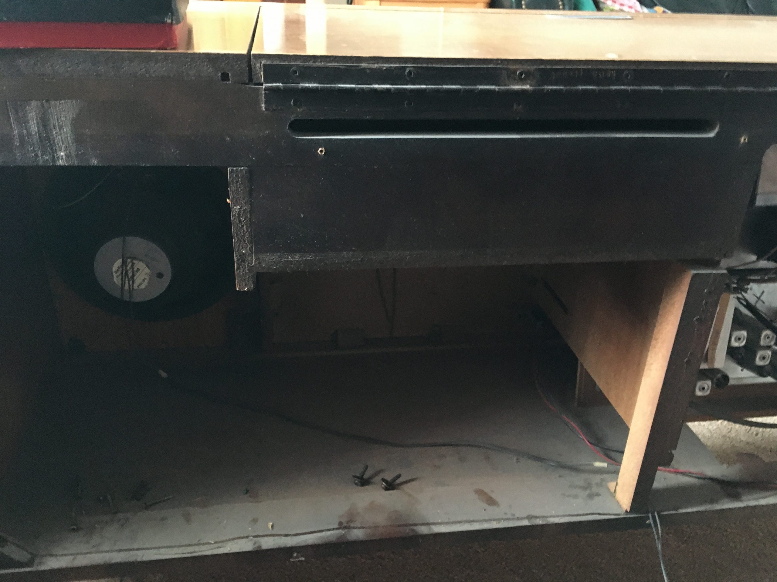
Inside of cabinet 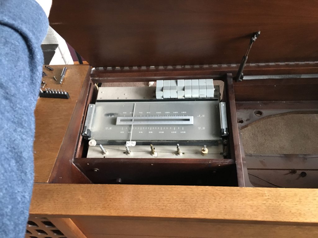
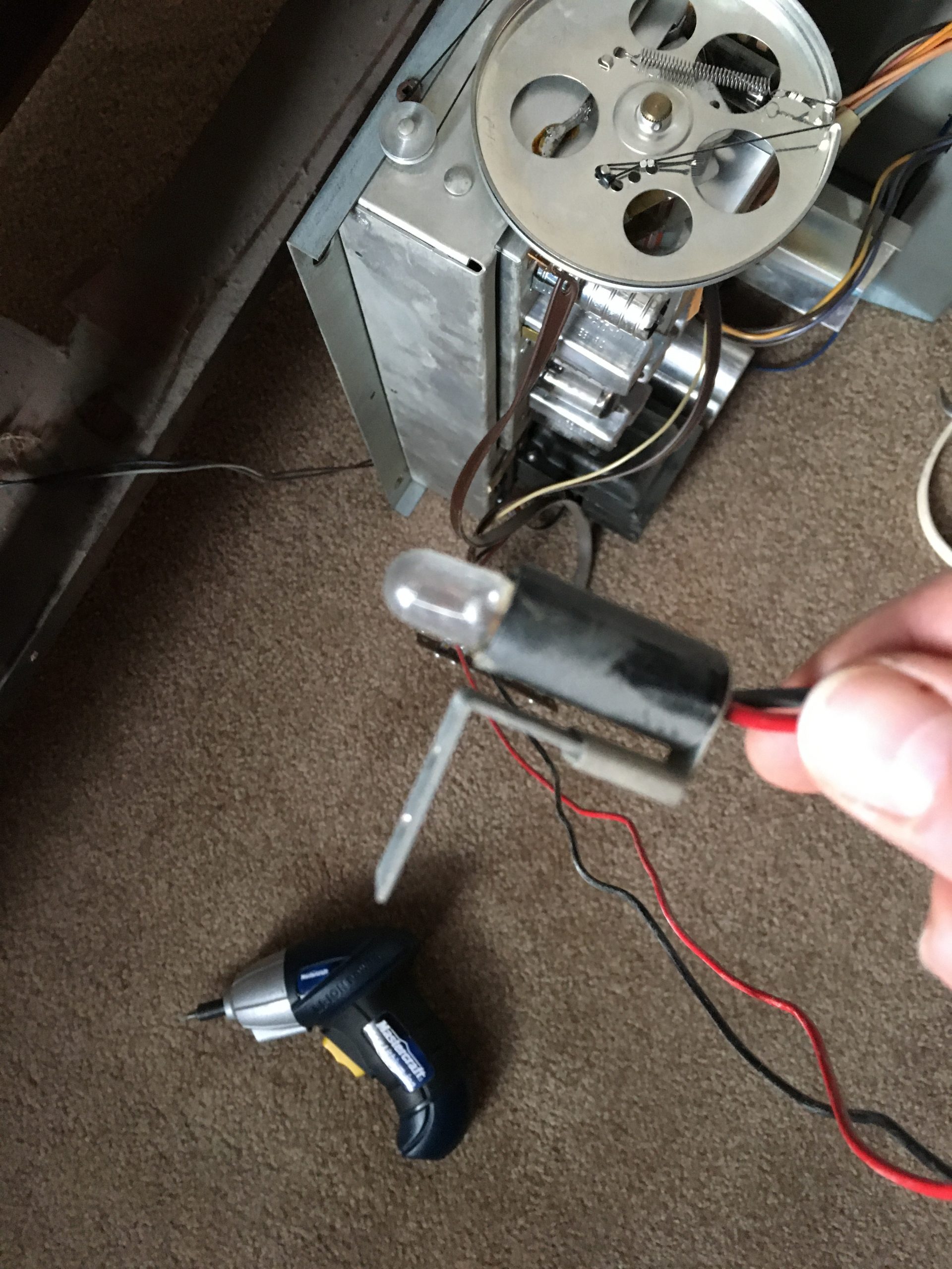
Old receiver 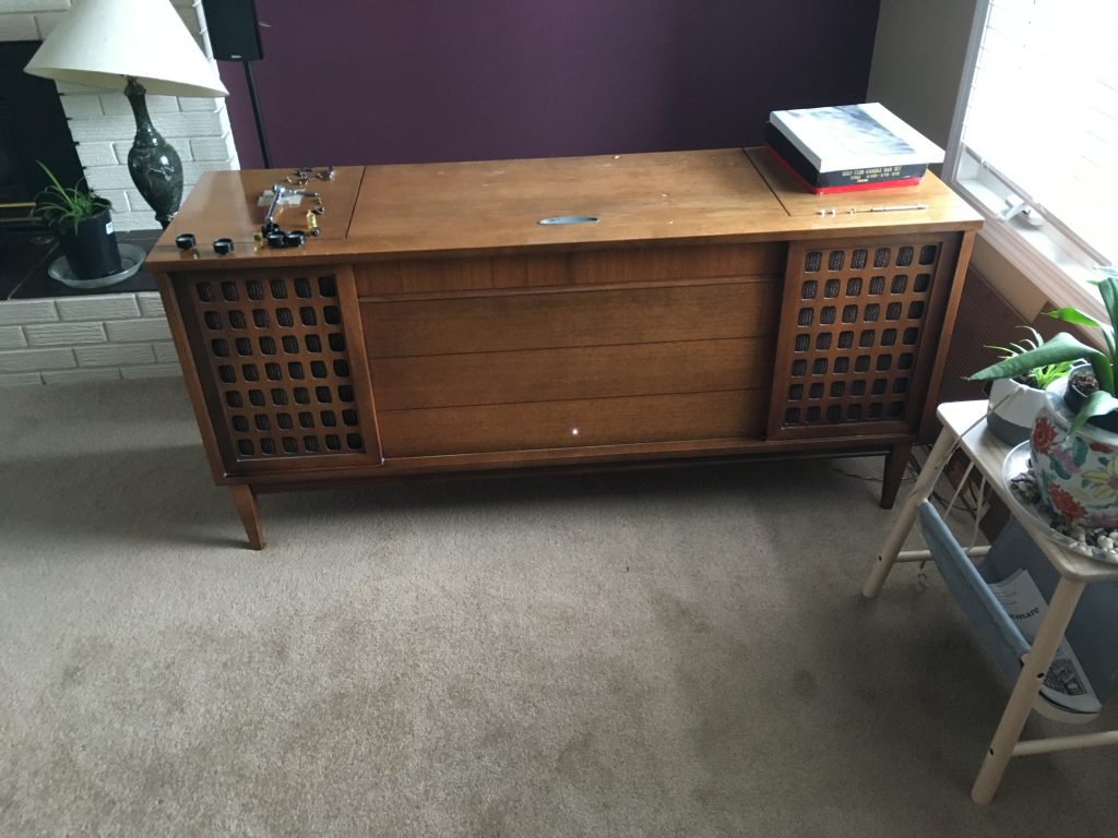
Cabinet w/power light on 
Power light, still working after 50 years. 
Speaker dust caps, now revmoved 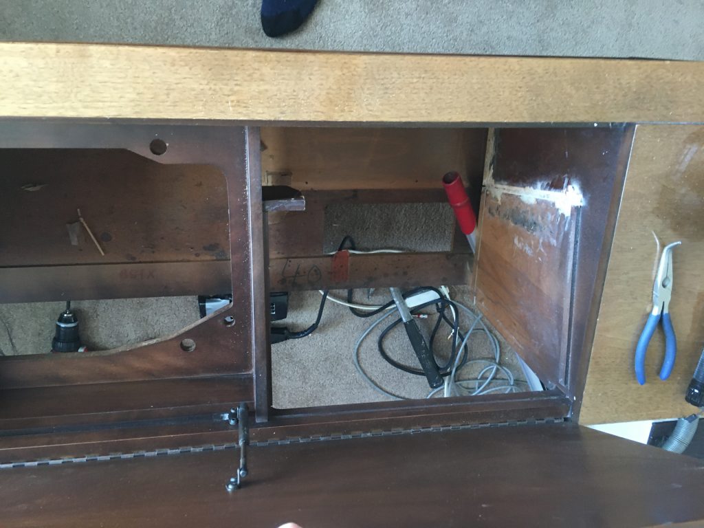
Sawing starts 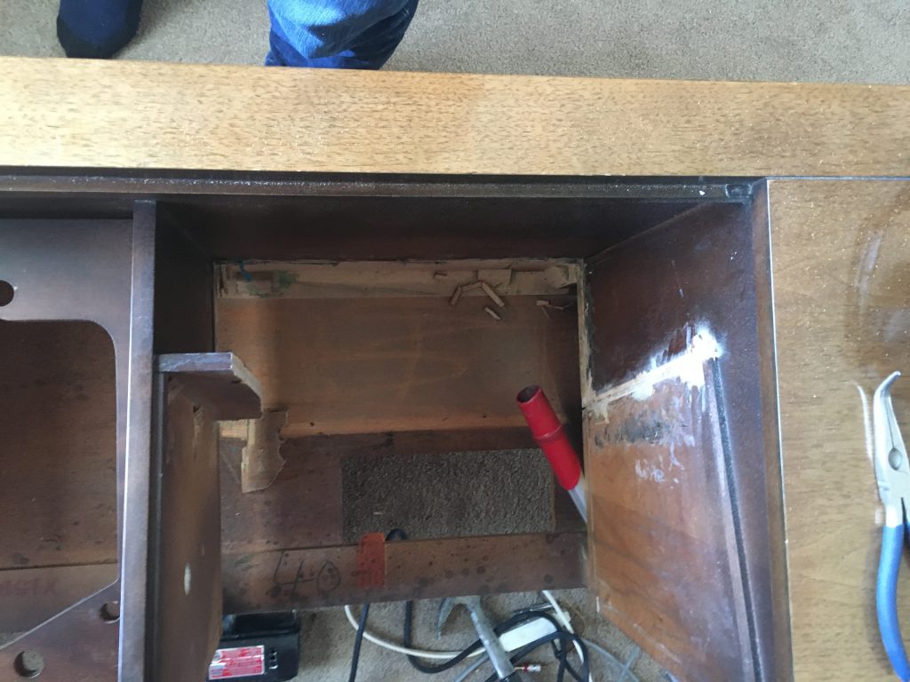

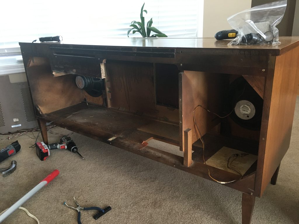
Hoping I don’t destroy the structural integrity.


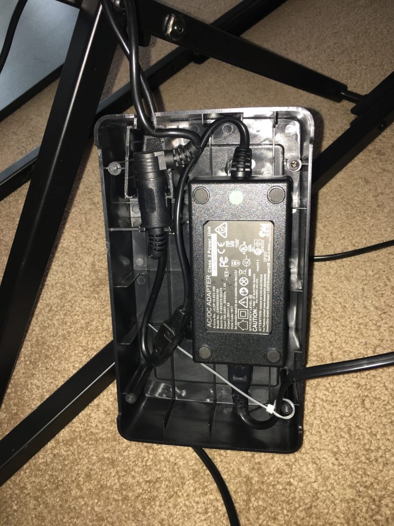
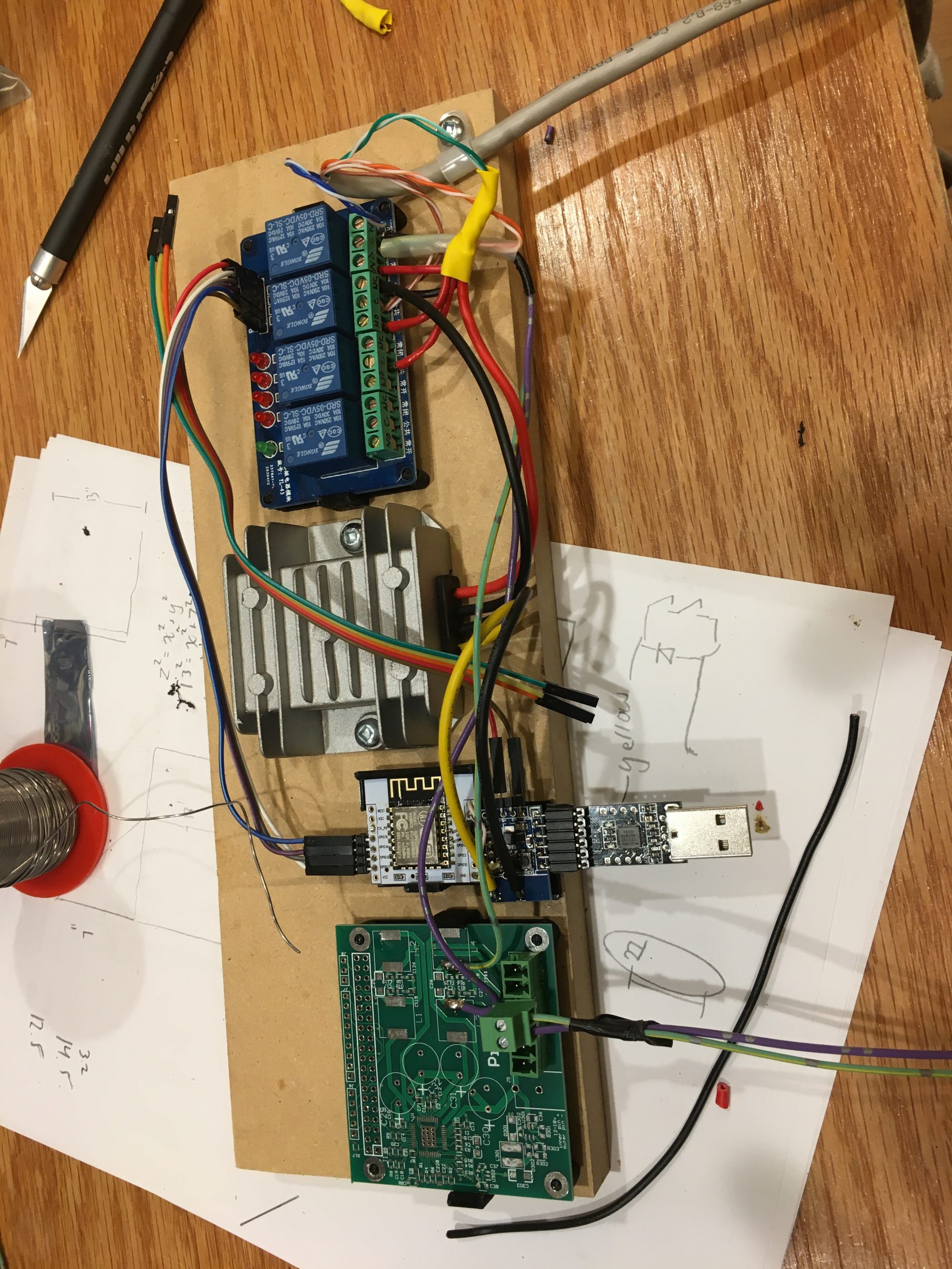
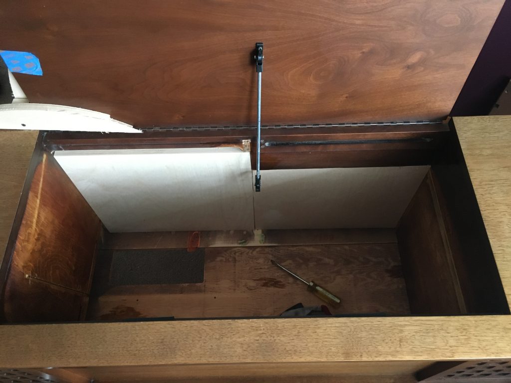
Next was installing the lift mechanism, this was done by tearing down a standing desk. The electronics were ripped apart, the desk top cut to fit, the legs cut off to fit. The button controls replace with a relay board that would do the same thing. Redundant limit switches were added to the standing desk. If it were to go too high, it would rip out the wood moulding that acts as a stop for the lid of the cabinet. An ESP8266 circuit was put in place with a simple web page:
Standing desk “electronics” 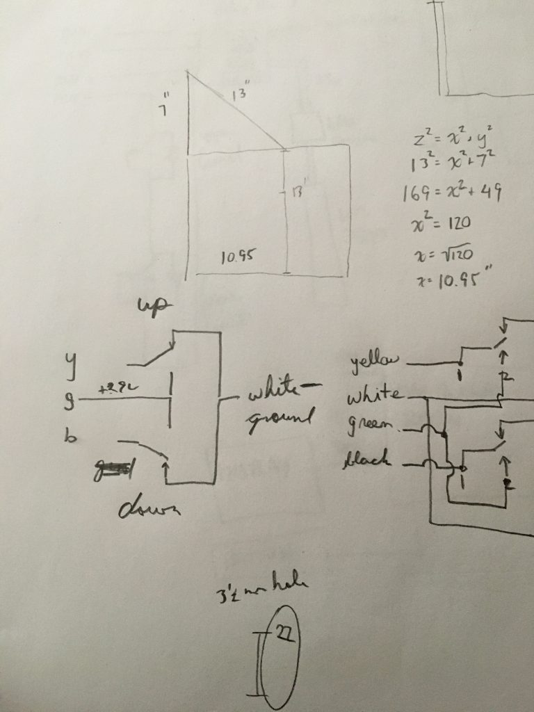
Circuit diagram, and lid support calculations 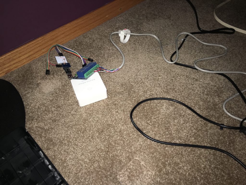
ESP and relay board subbed in for manual switch controls 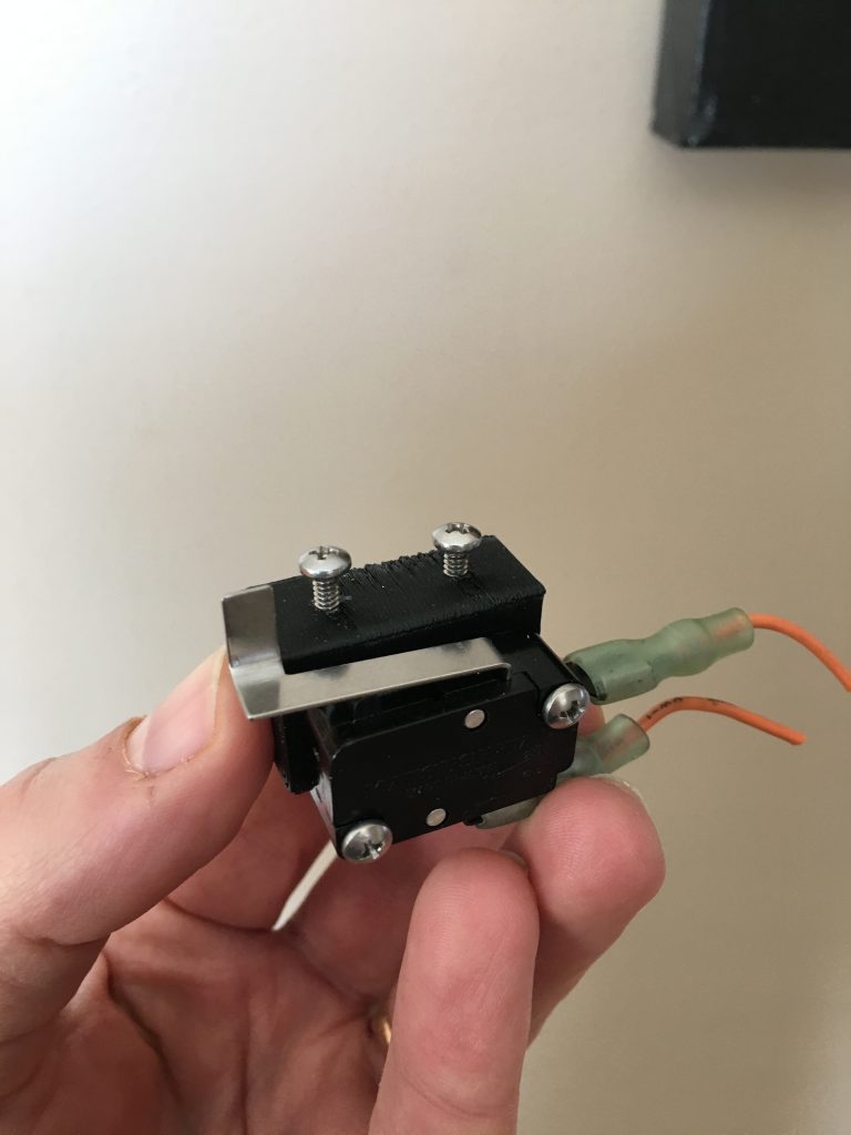
3d printed limit switch mount 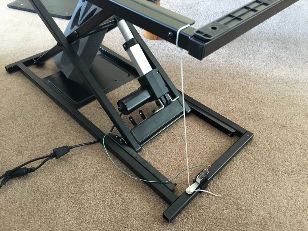
Really bush league redundant limit switch 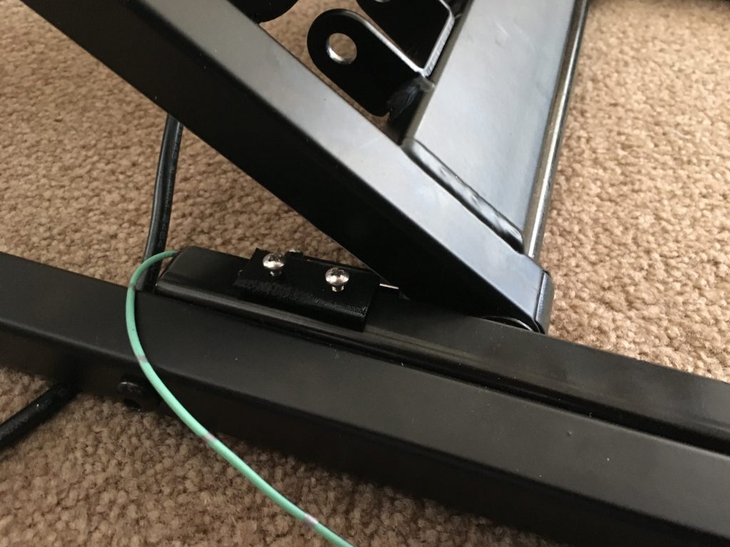
less bush league limit switch 
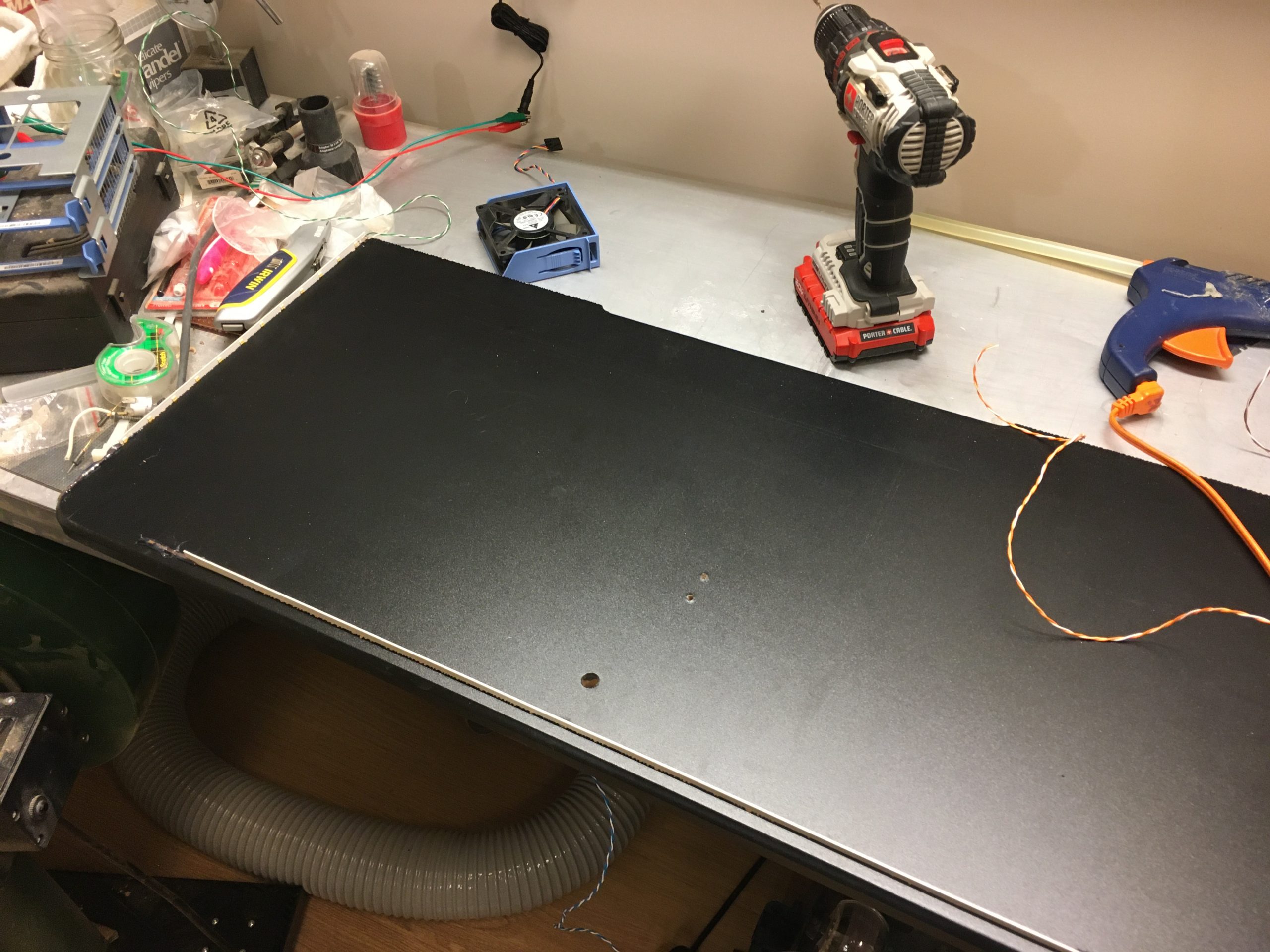
installing strip lighting around standing desk platform 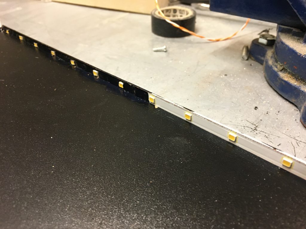
painting strips black to match 
test illumination 
start of bodged together control circuit 

The next steps were to enclose the cabinet properly. For this I used some awesome Baltic birch plywood, that may or may not have come from PK sound speaker holes. Then I installed the touch controls for the drink lift. The controls went between the speaker grill cloth and the plywood in which the speakers were mounted. The original stereo grill cloth had metallic fibers in it, which completely screwed up the cap sense controls, so it was replaced.
Birch plywood to enclose the cabinet for a nicer finish 
removing the old speaker grill cloth. The touch controls go beside the tweeter in the upper right 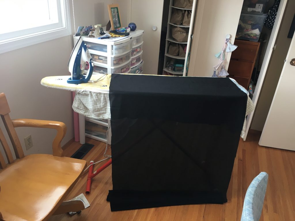
Ironing the new grill cloth so it lays flat. 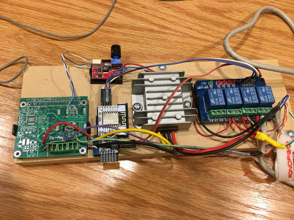
I added the lighting boost converter (red PCB) to switch under relay control.
This was changed to GPIO PWM later on.


At this point, the drink lift was largely working, and it was time at add some music back into the stereo cabinet, because it really needs it, given that there are speaker in it already etc. I’ve got a nice max2play system running, and oodles of homemade AMP and DAC boards for the raspberry pi, so this is (or should have been) fairly straight forward. For the PI however, I wanted a novel display. I have a couple of noritake VFDs that I got surplus from a place in Toronto (Hi Hudson), that I wanted to use. Given that my best days are behind me I want to start decreasing my inventory instead of collecting more sh*t. So they are a little lame but still retro. It took way too much time to integrate these displays into max2play/LMS. Hardware was an issue, I had to convert TTL serial to “real” serial. For S/W I originally went the Python route to make it work (as much as I truly despise interpreted languages). I got the displays working under OSX, and then had to bring up a secondary serial port on the pi (two displays and all). And as expected the python code spewed its guts on unicode, so in the end I rewrote the VFD code in ‘C’ as Kerninghan intended.
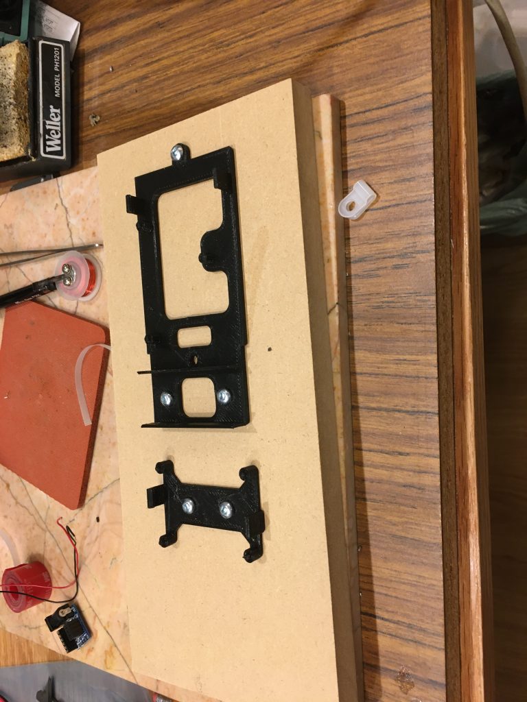
3d printed PI, fan and buck converter holder 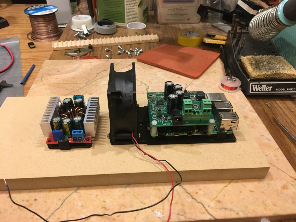
Mounted parts 
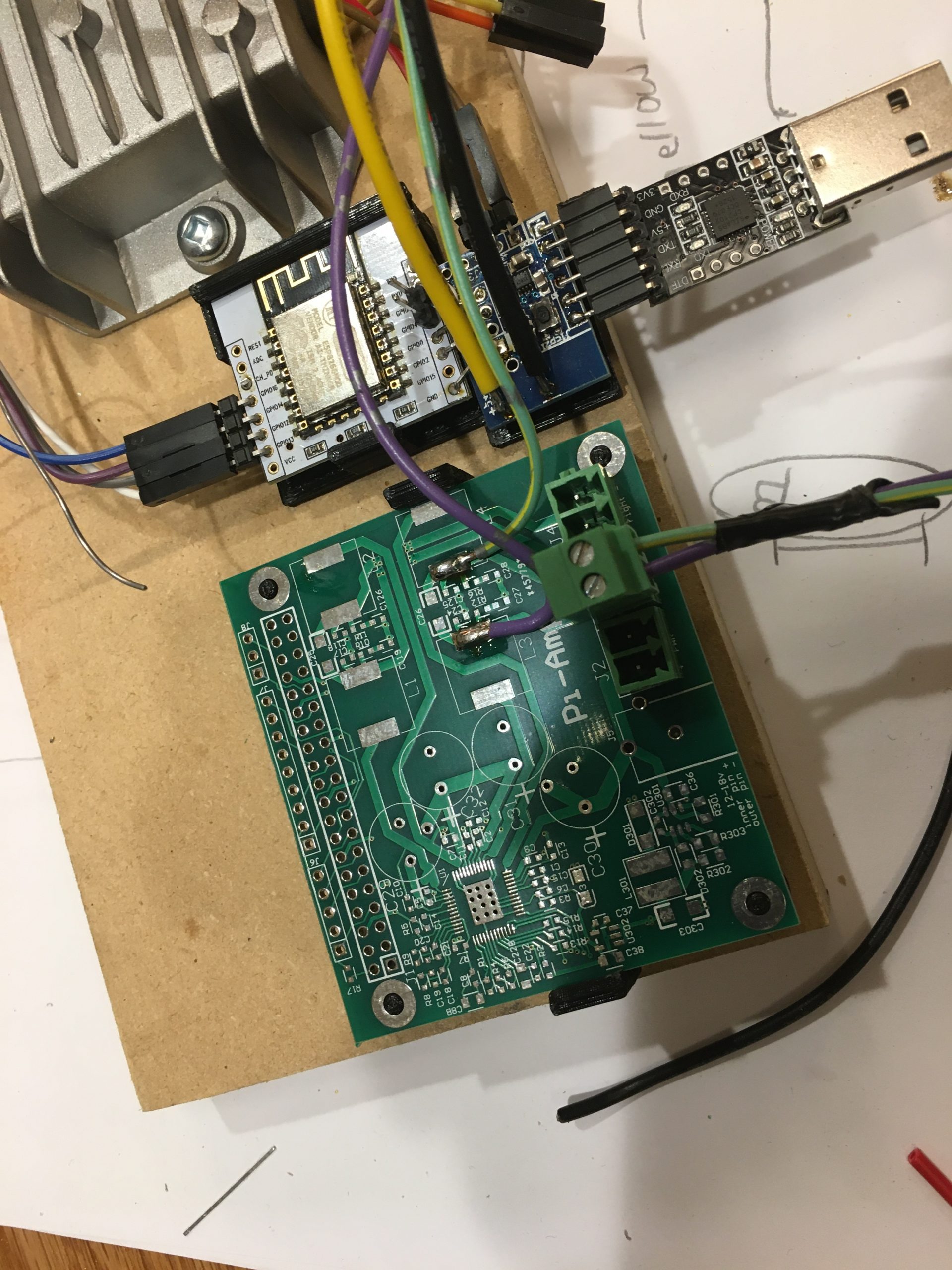
Dave talked me through the level shifting hardware 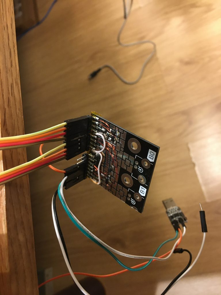
level shifter board for TTL to serial 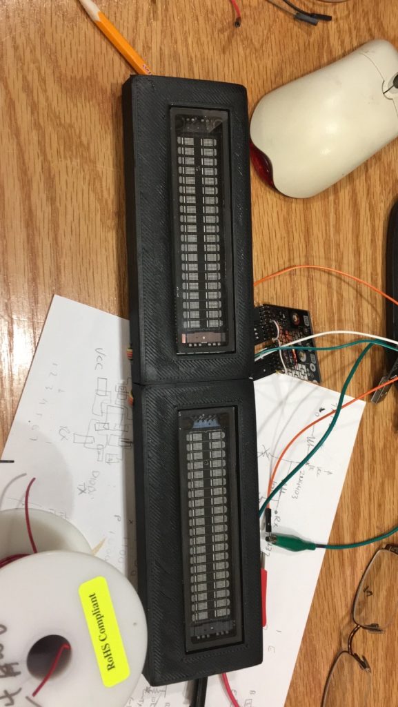
VFDs in 3d printed enclosures 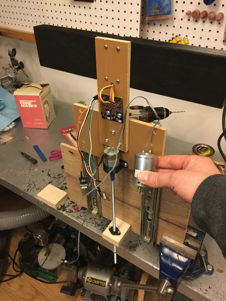
dual VFDs mounted on the linear actuator 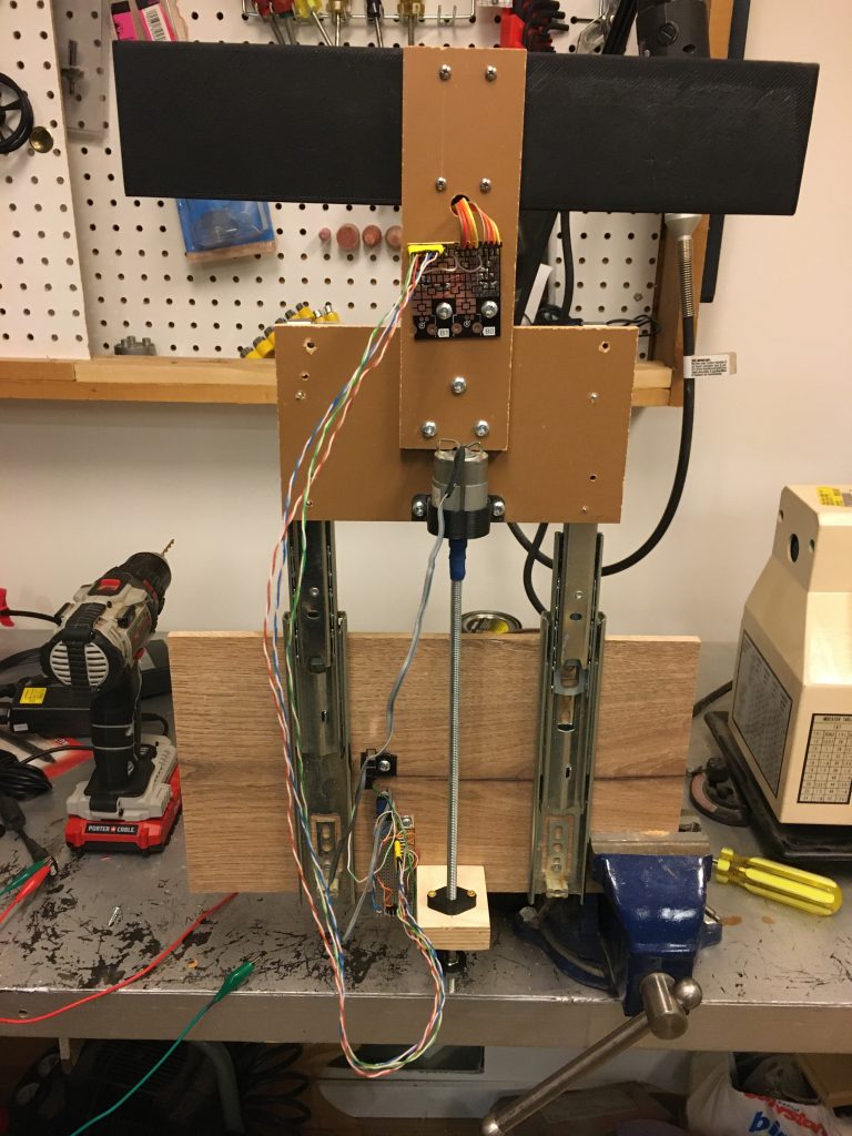

Now that I have another linear actuator, I needed all four relays on the relay board for the motors, so I had to steal the relay for the lights. This was relatively minor since I could switch the light boost converter board directly from the Esp8266, and get dimming at the same time via PWM. It is at this point I should mention my funny power supply situation. The standing desk is powered by a 29VDC 3A supply. My components at this point require the following voltages:
- 29 VDC – standing desk, and motor for VFD linear actuator.
- 18 VDC – PI AMP – takes 12-18V, 18 gives the best power output
- 12 VDC – supply for the VFD
- 5 VDC – supply for the ESP8266, Relay board and WS2812 RGB LEDS
- 33 VDC – supply for white led strips, this is a boost converter that takes 12-24VDC input. There are problems with the 24 VDC input at high currents, so I dialed this down to 16VDC
- 16 VDC – supply for the 33 VDC boost converter
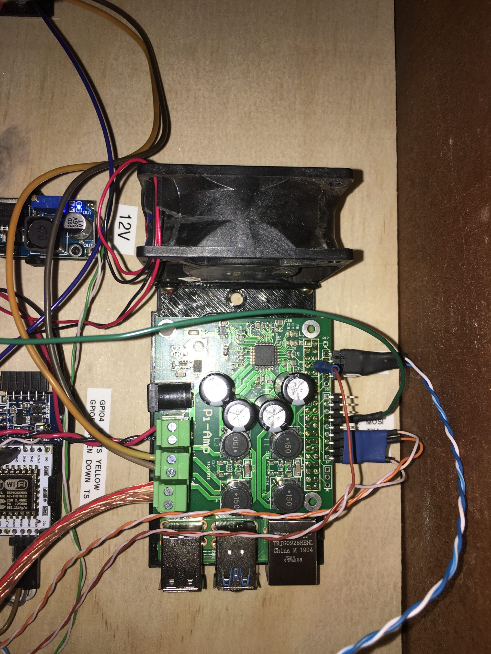
OK now that things were starting to come together, it was time to mount all the electronics on a single board.
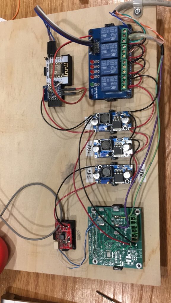
Crazy buck converter setup 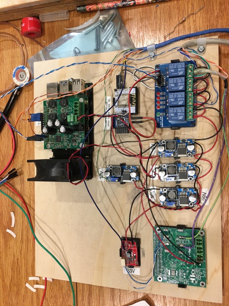
added pi 
Wiring for serial and RGB leds 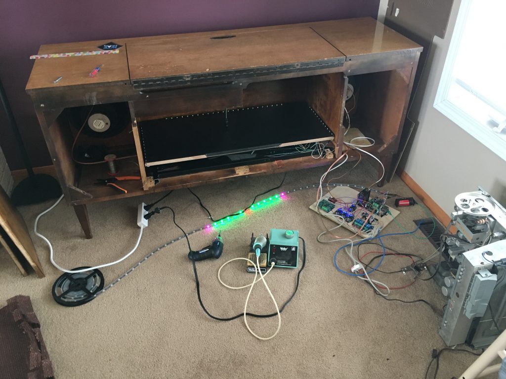
Final wiring 
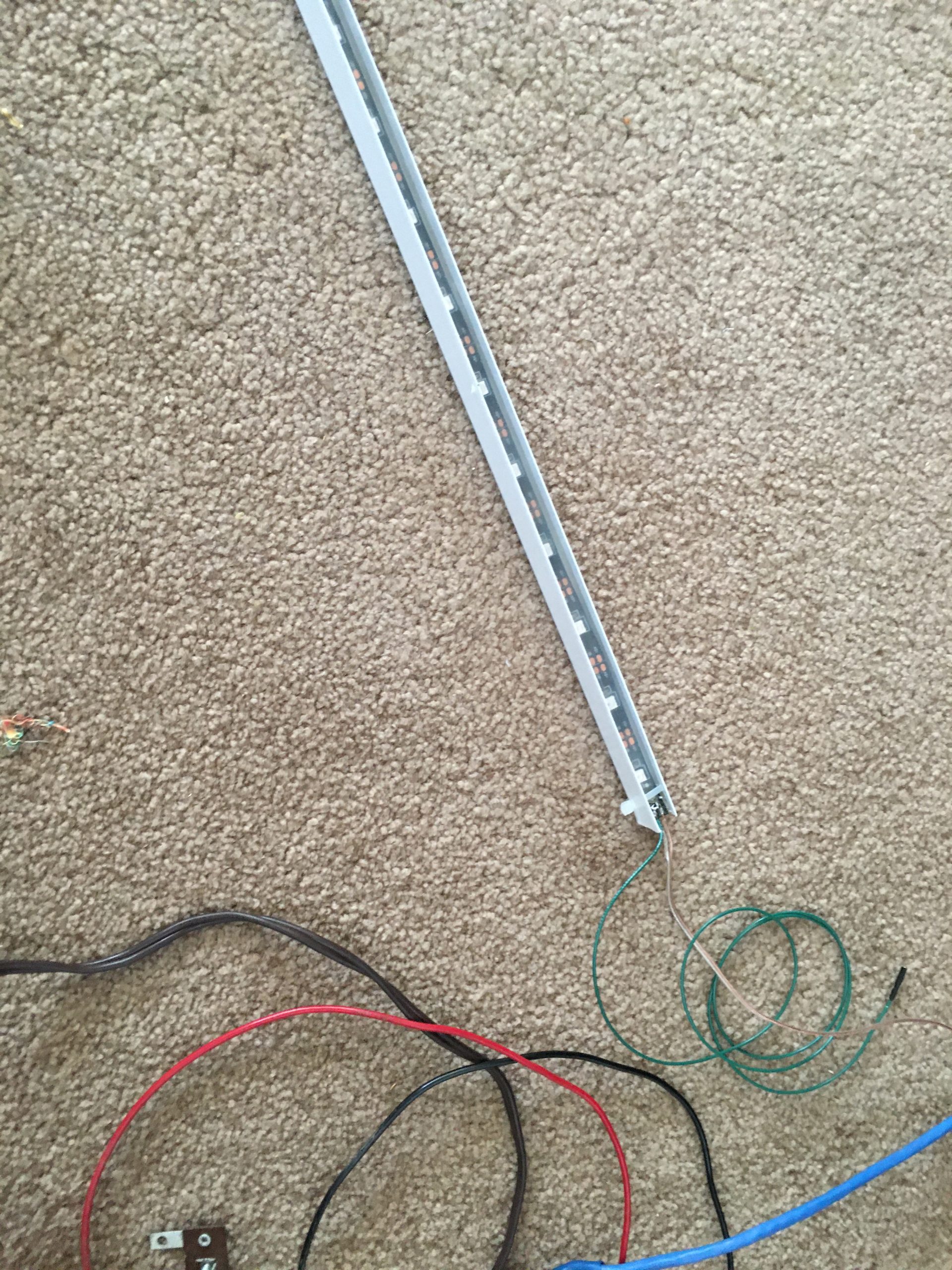
RGB strip before installation 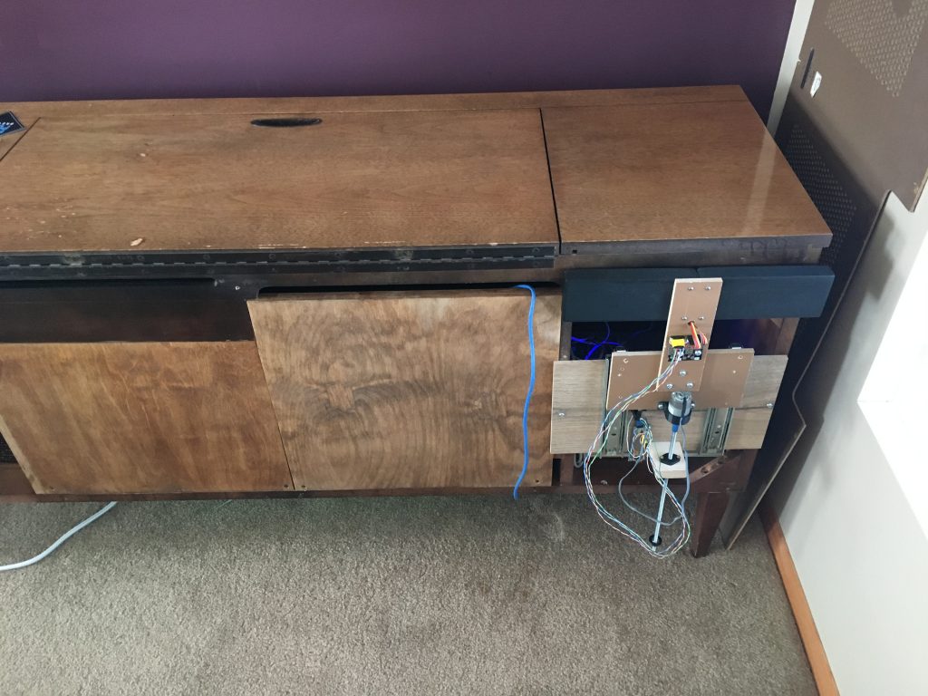
installation of display