Yet another clock.

Design
This time I thought that I would do a proper writeup of the clock. At the heart of it is a string of WS2811 lights that I got off of ebay, that were asking to be made into a project. The leds came in a 5 meter roll at 60 LEDs/meter. This dimension thus dictated the size of the clock with the diameter of the leds coming in at ~12.54 inches. (I use inches since the tools that I use like inches more than I do). So this was my design goal
- I wanted a ring of leds
- I wanted them to edge light the time marks on the clock
- I needed the electronics somewhere either separate, or on board, I decided to go with on board in the center.
- I had an LC Display at my disposal, so it should show the date, and heck the time as well, it also doubles as the menuing system (with buttons), so I have to take the display out to set the time
- I wanted hourly chimes, I was thinking Cuckoo Clock, but settled on Big Ben chimes.
Engineering Details
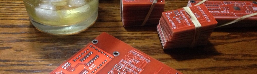
Since I was planning on building and selling a cappuccino PID controller I have a surplus of boards.  There are perfect (Atmel AVR) boards that can be used for just about anything since I over engineered them. If you have interest in buying one drop me a note at “info at zethus dot ca” and we can work something out. So the dev board has:
- AT90USB1287
- 128K external SRAM
- SD card slot
- SPI DAC and audio amplifier
- Nokia 6100 color LCD display (130×130 12 bpp)
- Battery backed real time clock
- I used PB 0 to bit bang out the WS2811 clock code.
Software for this was trivial, since I did all the heavy lifting a couple of years ago. It only required banging in the WS2811 driver, the rest was all there menuing, RTC, RTOS, Bootloader, Mass Storage and audio code.
For the physical machining I used a piece of 5/8″ MDF, cut with a 1/4 in end mill. The design was done in CamBam. It was largely a bunch of circles but with a lip for the LED strip to reside in. The acrylic was cut as four separate pieces, mostly because I’m cheap and get my acrylics from the garbage bin at the local acrylic place. I’m sure it would look a lot better had the acrlic been cut from one piece. As it is however, I think the equinox clock is probably a better visual design. The next build will look like this, and probably have the controller board external to the display. As I type this, I think having a largely hollow ring sitting on a base might be perfect. Then it is no longer a wall clock.
To put this together I first painted the MDF, then put the LED strip in the outer  circle of MDF. I tacked it down with hot glue. Next I put the center of the clock down, and laid the acrylic pieces on top. Once everything was aligned, I tacked them in place with more hot glue. Lesson learned here. I should have machine some holes in for machine screws to hold everything together, The hot glue doesn’t like to stick to MDF. Next I glued in the speaker, and the main board. The LC Panel is still separate, since I still need to pull it out from time to time, to set the clock. So it is held in place from the back with duct tape.
 I also decided to cut an acrylic window for the front to give it a more polished look. I was a little bit tricky to do the profile cut in the clock center after the fact, but worked well enough. the acrylic window cut was childs play. Did I mention that having a CNC router is awesome. They are not cheap but if you are a geek and have the space, I highly recommend getting one. Well this still looks like a lame writeup, but maybe it is a bit better than the last.
Now with more Sound!