 This installment is a whole home audio system. I wanted something like a Sonos, but cheaper, and wanted to use my own speakers, instead of being held hostage to small drivers. So what I ended up with was a “max2play” based system with my own versions of a Hifiberry DAC pro and Hifiberry Amp+ boards, In addition I added a 320×240 ili9341 spi touch screen. This is a standard screen, but I had to modify the device tree overlay, since the layout of my amp/dac boards used GPIOs that were not standard for these displays. I built the boards before looking at any of the software available, oh well. I also used my rotary encoder/charlieplexed LED board for VU-meters and input. There are four gpio buttons on top of the device to give hardware control over play/pause,prev,next and shutdown functions. I used iPeng for control of it all. The main server player mounts music from a NAS box, or I can stream, usually from radio paradise.
Currently I have 5 of these players (or variations thereof, with a 7 inch screen) around the house. The audio is synchronized between all the players. It is quite fantastic. Just in case anyone wants to follow in my footsteps, I’ll outline what I’ve done. I find the hardware to be the fun part, but the software was more than a little bit challenging, and I’ll give some pointers and code for the VU-meters toward the end of the post.
HARDWARE
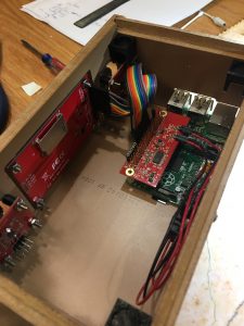
The guts of an “amp” box are shown here. You can see the pi with my 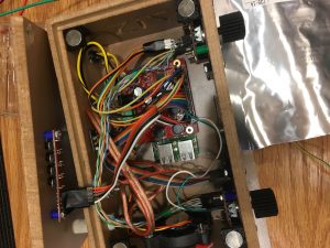 custom amp daughterboard. Along the right hand side is a breakout for the LC panel and gpio. The two push button encoders are daisy chained off a software SPI interface, there is a 5V buck converter on the left side that is used for the fan at the bottom. The fan is 12v but running it at 5V allows it to run slow enough to be inaudible, which is sort of the point with stereos. The lid of the box is held on with magnets.
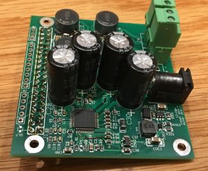
This is the “amp” daughter board it is powered by 12-20v and supplies power to the PI. This board is compatible with the hifiberry amp+ drivers and max2play code, since it uses the same TMS chip. Note the I/O pins on the left hand side. The speaker outputs are on pluggable connectors.
This is the schematic for the pi amp board piamp
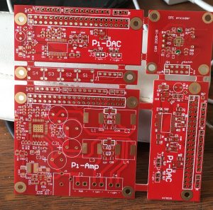
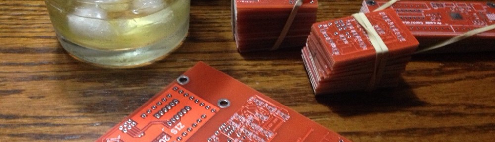
Here is the second board run I did for the AMP, it also had my first run of two DACs, an encoder, and the top button board
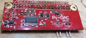
The populated dac board, with the 44 and 48 khz oscillators. Note this board is smaller than a hifiberry dac, the audio outputs come out to 0.1″ headers for more flexibility. The extra breakout pins can be seen at the top of the photo, this works great for adding LC panels, but makes this “hat” impossible to fit into a standard case. If I was to ever do this again, I might try routing the traces to the other side of the board, but then again keeping the analog and digital portions of these boards separated as much as possible is probably a good thing.
The schematic for the DAC board is here. Protel Schematic
Note the wiring of the ID eeprom to the pi header pins is off by one.

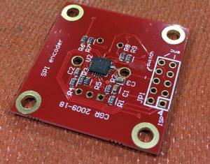 The encoder board is the same board that is described about 8 years ago in this blog (I had trouble finding it, but all the info is here anyway). I finally got around to pressing it in to some kind of service. It is using an attiny84, and it talks to the Pi over the SPI bus. This was made especially difficult, since the ’84 only has a usart (no hardware spi support) and the fact that the pi had all its hardware SPI ports. There are good software drivers for the pi (pigpio) but the spi usart driver for the tiny84 does not implement CS, and that was hand rolled. In any case the PI determines the audio levels for left and right, and transfers that value (0-15) over spi to the encoder board. The byte coming back is any change in the encoder value. The encoder will light the LED corresponding to the sent value.
encodersch
Note: power and ground are reverse on this schematic
The rest of the case was 3D printed/CNC routed.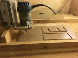 The bottom and side panels are simply glued together. The clear acrylic window that houses the encoder/VU-meter is CNC’d and pressed into place with a vice, then held in place with the bolts holding the encoder board. The encoder knobs and magnet mounts and top buttons are 3D printed. Here are some pictures of the manufacturing:
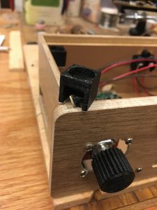
SOFTWARE
The software setup is largely handled by the Max2play installation. I have a single driver that I’ve included to read buttons, the encoder, and drive the VU-meters.
I also had to remap the device tree overlay for the changed pins in the rpi-display.
The code for the vu-meters will also be included here for anyone interested.
Last edited Oct21. Stay tuned for this software section to be filled out.